
What’s in the Box?
A standard Prospero unit includes:
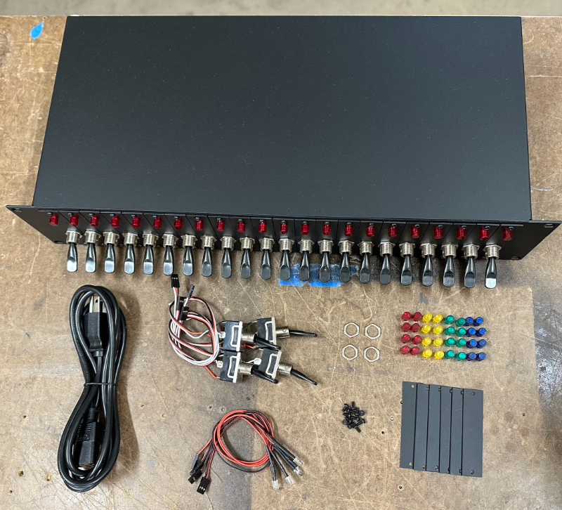
- Prospero cue light panel (1) with (22) switches installed
- Power cord (1)
- Spare parts kit, including:
- Red, Green, Yellow, Blue colored lenses, (8) each
- Spare switches (4)
- Spare switch nuts (4)
- Spare LEDs (4)
- Blank plates (single-wide) (6)
- Spare screws (12)
Note that this is what ships from our factory. Prospero units from rental houses may ship with a different parts package.
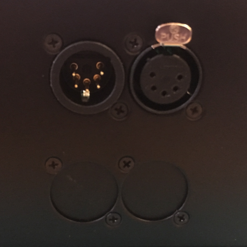
How do I know if I have a Prospero v2 or v3?
The outside case of the v2 and the v3 are identical (and can be physically upgraded - v3 is backwards compatible with v2), but v3 has an ethercon connector below the DMX ports.
Setting DIP Switches
- All DIP switches on the back of the unit must to be set to OFF (down) for the unit to operate in v3 mode.
Prospero v3 can operate in “v2 emulation mode”. If the start address is set to anything other than 0 on the DIP switch module, the unit will operate as a v2 unit, with the functionality described in the  Prospero v2 User Manual.
Prospero v2 User Manual.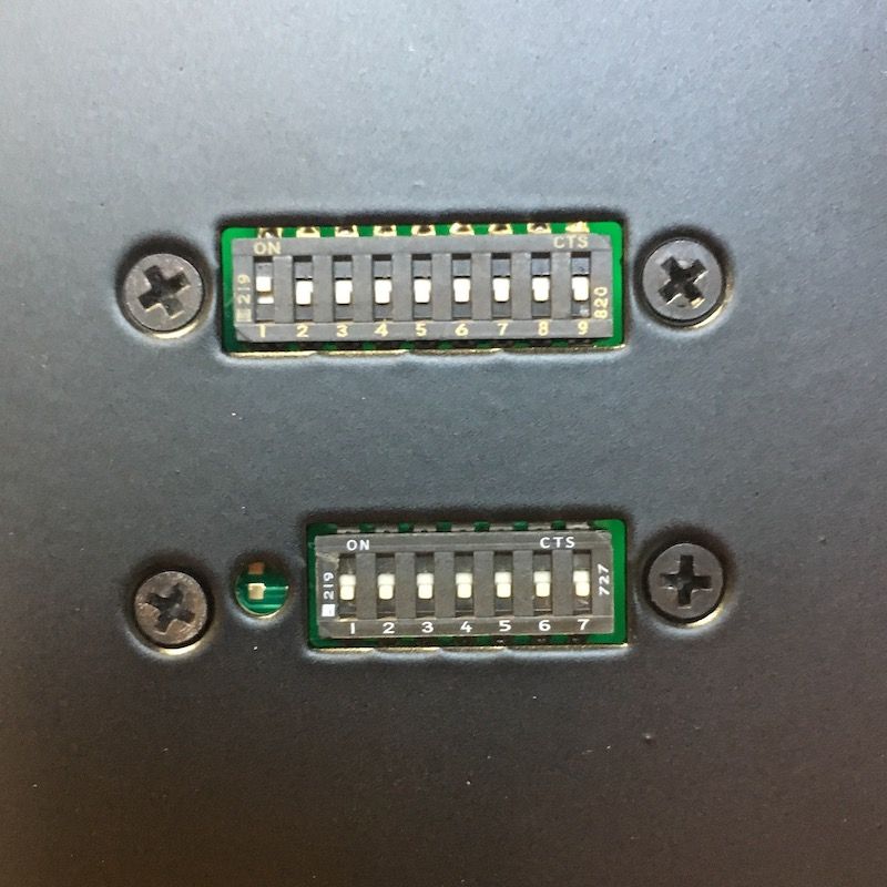
The DIP switch module can be completely unplugged from the main board if you want it to always be in v3 mode. Be aware that this will disable the configuration reset function as well - the module will need to be reconnected before the unit can be reset.
Rearranging Switches & LEDs
Individual switch plates can be rearranged as needed, and blank plates can be inserted between switches to create logical and tactile groups. Blank plates are available in single- and 4-wide sizes.
Rearranging Switch Plates
The switch plates are held on by two screws. Remove those screws, and the switch plates can be moved around and reinstalled in different slots.
Once the switch plates are arranged (and any blank plates installed), you can swap out the LED color on each plate by replacing the LED lens.
We recommend only using hand tools or low-torque power tools to install and remove the screws, as they can be very hard to remove if they are sheared off in the panel.
Need more plate screws? They’re 1/4” long, 4-40 pan-head stainless steel screws, available from McMaster-Carr (Part #91249A105).
Removing LED Lenses
- Push the lens all the way in towards the back of the panel.
- Remove the LED from the lens.
- Once the LED is removed, push the lens back towards the front of the panel.
- Either use your fingers to get one of the tabs out past the hole, or once pushed all the way forwards, you can rotate the lens off-axis to get a retaining tab to pop free.
- Once a tab has popped free, the whole lens should come straight out.
Installing LED Lenses
- To install the new lens, don’t try to push it straight in.
- Angle the lens so that you get a couple of the retaining tabs into the hole, then rotate it to lever the lens against those to push the other tabs in.
- Once you have all four tabs in, push the lens all the way in to the ledge.
- Install the LED from the rear.
- Push the lens towards the front of the panel until the back of the tabs are against the plate.
With the currently-shipping LEDs, this will hold the LED in place. If you have an older half-size LED, you may need a dot of hot glue to hold the LED in place.
Repatching Switches & LEDs
Inside the unit, the switches and LEDs can be repatched to the main control board to match the setup of the front panel.
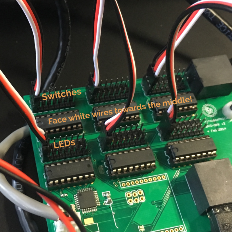
- The "top" row (away from the switches) connects to the switches while the "middle" row (closer to the switches) connects to the LEDs.
- Switch 1 is the farthest to the left, Switch 24 is farthest to the right, and they're patched in banks of 8.
- The black or brown wire for the switches faces towards the back of the panel. The black or brown wire for the LEDs faces towards the front of the panel.
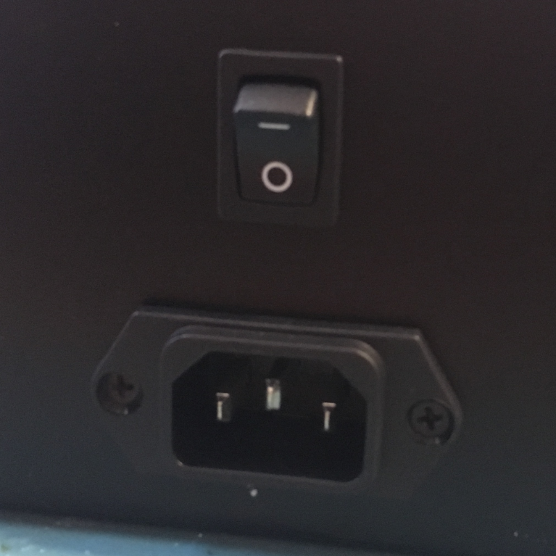
Connecting Power
There are two options for powering the unit:
- Wall power (95-250VAC): Plug the included power cord into the unit’s IEC connector. When using wall power, the power switch will control device power.
- PoE (802.3af Class 0, or 48VDC passive): Connect the unit to a PoE switch or power injector via the unit’s ethernet port. When powered by PoE the power switch does not turn the device off.
When servicing the unit with the lid off, we always recommend unplugging all external connectors.
Connecting Data
There are two options for connecting data to the unit.
- DMX: The DMX ports on the back of the device are a straight pass through - rather than a DMX In and DMX Out, they're both connected to a DMX transmitter as long as the panel is switched on. This lets you hardwire backups inline: which device is in control is determined simply by which one is turned on.
- Ethernet: The v3 uses ethernet for configuration settings, as well as outputting sACN universes to control cue lights. If ethernet is already connected for PoE, you’re all set. If not, connect the unit to your network switch via the ethernet port on the back.
These options can be used individually or simultaneously - see  Prospero v3 User Manual for details on data output and configuration.
Prospero v3 User Manual for details on data output and configuration.Turning the Panel On
- If powering via power supply, flip the power switch on the back of the unit to On (up).
- If powering via PoE, the unit will turn on as soon as power is available.
When you turn the panel on, all the LEDs should light up from the center outward. Then DMX output will start, and the LEDs will reflect the switch state.
Having problems? Check out the  Prospero Troubleshooting page for answers.
Prospero Troubleshooting page for answers.