
Main Board Release Notes - v1.3
Board Replacement Instructions
- Unplug the unit from power source.
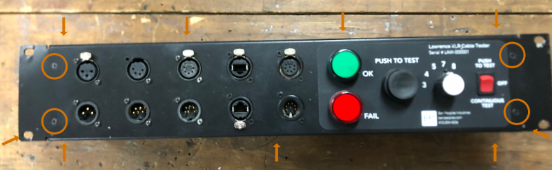
- Remove 15 screws from all sides except the back of the case:
- 4 screws on the face are circled.
- Arrows indicate screws on the top (4), bottom (3), and sides (2 on each side).
- There are 4 screws in the back, which DO NOT need to be removed.
- Case will separate into two pieces. Unplug 5 molex connectors and 2 ribbon cables from existing main board.
- Remove the 12 screws mounting the main board to the front face.
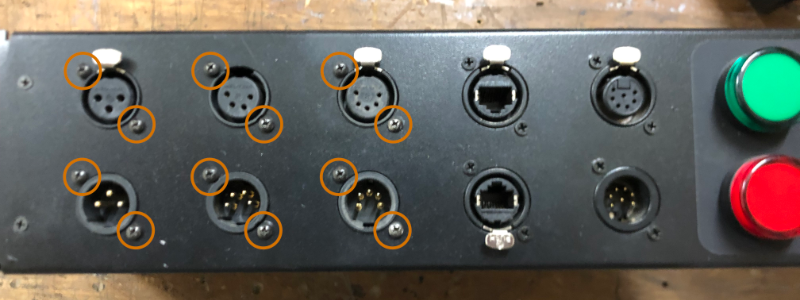
- Old board will separate. Use 12 screws to reinstall new board with female connectors up.
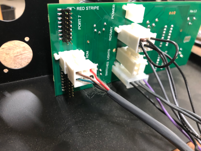
- Plug in the cables:
- Plug in the ribbon cable to the 7p XLR module on the top of the new board.
- Plug in the RDM 6p molex (connects to back of the case) below it.
- Plug in the ribbon cable to the 8p RJ45 jack on the bottom of the board.
- The remaining wires should be bundled. Plug them into the remaining 4 molex connections.
- Reattach the 2 case halves with the remaining 15 screws.